
The short answer: antistatic ABS needs four classes of evidence
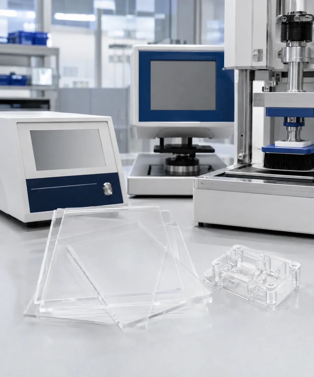
A reliable antistatic ABS validation covers electrical performance, optical performance, durability and molding consistency together. Clearastatic's published property range for DGK-ABS KJD890TM is 10⁸-10¹⁰ Ω/□ surface resistivity. Site selection content uses at least 85% light transmission at 2 mm as the baseline, while disclosed project samples reached at least 87% transmission with haze below 8% and typically measured 2×10⁸-8×10⁸ Ω/□. These figures become comparable only when the method, thickness, conditioning environment and electrode are stated. They do not replace acceptance testing on the customer's final part.
| Validation dimension | What to record | DGK-ABS KJD890TM site data | Decision focus |
|---|---|---|---|
| Surface electrical | Method, electrode, temperature, humidity, location and read time | Published range 10⁸-10¹⁰ Ω/□; project typical 2×10⁸-8×10⁸ Ω/□ | Whether locations and batches stay inside the project range |
| Optical | Thickness, transmission, haze and visible defects | Baseline ≥85% at 2 mm; project typical ≥87% with haze below 8% | Whether the real viewing or machine-vision task is met |
| Durability | Before-and-after low humidity, wiping and water treatment | 10⁸-10⁹ Ω/□ after 500 alcohol wipes in the cited project | Whether a large order-of-magnitude drift or surface failure occurs |
| Molding consistency | Wall thickness, flow direction, gate and flow-end locations | Spread within 0.5 order of magnitude on the cited part | Whether plaque performance transfers to production geometry |
The values above come from existing Clearastatic property information and an anonymized customer project record. They describe specific material, samples and process conditions; they do not promise identical performance for every thickness, color, mold or environment.
What is the difference between surface resistance, surface resistivity and volume resistivity?
Surface resistance is the measured resistance along a sample surface between defined electrodes and is reported in Ω. Surface resistivity is a normalized expression of surface conduction and is commonly reported in Ω/□. Volume resistivity describes current flow through the body of a material and is reported in Ω·cm. The exponents cannot be compared or converted without the geometry and method. The current DGK-ABS KJD890TM property table on this site uses surface resistivity and Ω/□; a project report using a surface-resistance method should continue to use Ω.
ASTM D257 covers DC resistance, surface resistivity and volume resistivity of insulating materials and notes that surface contamination can affect results. ANSI/ESD STM11.11 addresses surface resistance measurements for planar materials, including equipment, specimen preparation and environmental conditioning. A report should name the chosen method instead of presenting an unqualified number.
How should surface electrical performance be validated?
Start by defining the test object. Resin pellets do not represent a molded component, so use at least an injection-molded plaque and the actual part. On the real geometry, select repeatable positions near the gate, in the middle of the flow path, at the flow end, across thin walls and in high-shear areas. Record thickness, surface condition, temperature, humidity, test voltage, electrode and stabilization time. Test batches and locations in the same sequence.
Next, separate a published material range from a project typical range. DGK-ABS KJD890TM is listed at 10⁸-10¹⁰ Ω/□ surface resistivity. Molded medical monitor panels in the case below measured 2×10⁸-8×10⁸ Ω/□. That narrower result is project evidence, not a substitute for the acceptance range that another customer must set from ESD sensitivity, grounding design, component geometry and use environment.
Why must transmission and haze be reported with thickness?
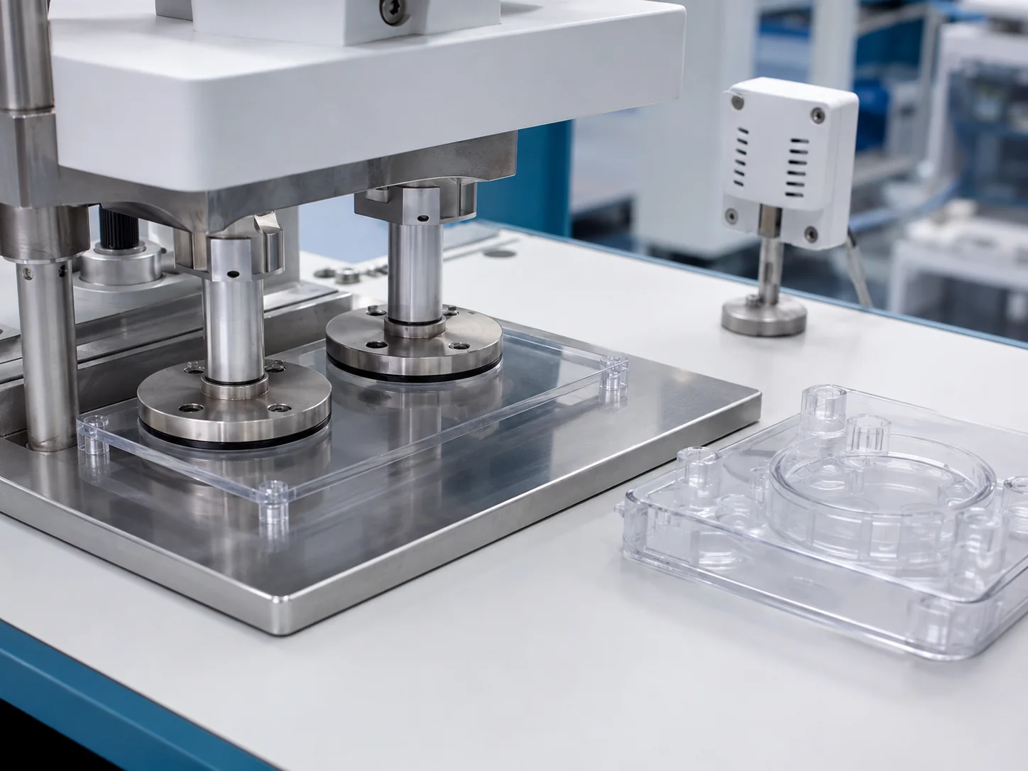
The optical result of transparent antistatic ABS depends on thickness, texture, color, drying and molding shear. ASTM D1003 addresses haze and luminous transmittance of transparent plastics. A useful report includes sample thickness, light transmission, haze, method and visible defects. The phrase “high transparency” alone cannot support a sourcing comparison.
Clearastatic site selection content uses at least 85% light transmission at 2 mm as the baseline for DGK-ABS KJD890TM, while disclosed project-sample data report at least 87% transmission and less than 8% haze. A molded-part review should also inspect splay, bubbles, flow marks, weld lines and local cloudy areas. In the first medical monitor panel trial, average transmission reached 87%, but a cloudy region appeared in a wall section about 1.2 mm thick. Passing one average optical number did not mean that appearance and local optics had passed.
How should low humidity, wiping and water-treatment durability be checked?
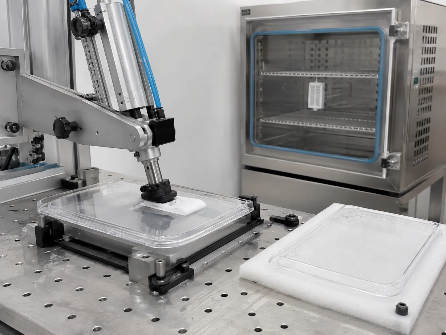
A useful durability test resembles actual use. A medical panel exposed to disinfectant needs a defined alcohol concentration, wiping load, path and number of cycles. A part used in a dry plant or winter environment needs low-humidity conditioning. A washable component needs the same electrical method and positions before and after water exposure. Keep untreated controls and record visible surface damage as well as electrical drift.
Clearastatic project records for DGK-ABS KJD890TM show surface resistivity remaining within 10⁸-10⁹ Ω/□ after 500 alcohol wipes, a change below one order of magnitude. The same record reports a change below 2 times at 15% RH and an increase below 30% after 24 hours in 60°C water. These conditions illustrate an evidence path and an existing boundary. Each customer should redefine the protocol for its own cleaner, temperature, service life and geometry.
Real customer case: validating a clear medical monitor panel
Case-source note: the following account comes from Clearastatic's medical monitor panel project records. The customer name and identifying information are withheld under confidentiality requirements. The molding, wiping and low-humidity figures are values already disclosed on this site.
The original design used an antistatic coating on standard clear ABS. The panel passed electrical and optical checks at shipment, but staff in the ICU wiped it with 75% alcohol several times per day. After three to six months, frequently wiped areas lost static control, attracted dust and interfered with reading the display. The project therefore changed its acceptance logic from “passes once at shipment” to “passes on the initial molded part, after wiping, after low-humidity conditioning and across multiple part locations.”
For the first DGK-ABS KJD890TM trial, the resin was dried at 85°C for four to five hours, processed at 195-210°C and molded at 70°C. The part reached 87% light transmission and 3.2×10⁸ Ω/□ surface resistivity, but a slight cloudy spot remained near the 1.2 mm thin-wall flow end. The engineering team raised the mold temperature to 75°C and changed the filling profile to slow-medium-slow. The cloudy area disappeared on the second trial.
| Validation item | Original coated ABS | DGK-ABS KJD890TM |
|---|---|---|
| Molded-part transmission | About 87% | At least 87% |
| Initial surface resistivity | Passed at shipment; exact value not disclosed | 2×10⁸-8×10⁸ Ω/□ |
| After 500 wipes with 75% alcohol | Surface layer failed | Remained within 10⁸-10⁹ Ω/□ |
| After 15% RH conditioning | Large increase | Change below 2 times |
| Across-part variation | No complete record established | Spread within 0.5 order of magnitude |
The adjusted panel entered batch use. Clearastatic delivery and after-sales records show about 150,000 parts delivered, with no static-related dust complaint in the recorded period. That result is evidence for this confidential customer, component and process window; it is not an unconditional performance guarantee for every DGK-ABS KJD890TM project.
What should sourcing and engineering teams put in the acceptance checklist?
| Field | Recommended entry | Avoid |
|---|---|---|
| Electrical requirement | Metric name, unit, method, electrode and range | “Resistance of 10 to the eighth” |
| Sample condition | Batch, molded geometry, thickness and locations | Pellets or an unidentified plaque only |
| Environment | Temperature, humidity, conditioning and read time | “Room conditions” |
| Optical requirement | Transmission, haze, thickness and defect limits | “Transparent” |
| Durability exposure | Cleaner and cycles, low humidity, water treatment and aging | Approval based on “permanent antistatic” wording |
| Decision boundary | Application conditions, exception handling and third-party requirements | Treating a material value as a final-part value |
At project start, use the DGK-ABS KJD890TM property and molding data to define an initial range, then use Clearastatic's material testing and sample-validation capabilities to turn it into acceptance conditions for the real component.
Data notes and scope
Product range, processing conditions and property values draw on Clearastatic's DGK-ABS KJD890TM site information reviewed on September 5, 2026. The customer case comes from anonymized medical-monitor panel molding, wiping, low-humidity, delivery and after-sales records. Test design follows the metric and method boundaries defined by ASTM D257, ASTM D1003 and ANSI/ESD STM11.11.
This article supports material screening and validation planning. It is not a medical-device, semiconductor-product or other end-product certification. The project owner should confirm the applicable regulation, standard revision and customer acceptance criteria for the actual use.